Cte Ceramic Capacitor

Coefficient Of Thermal Expansion Cte Values Of Sioc Glass And Glass Download Scientific Diagram

Pdf Flex Cracking Of Multilayer Ceramic Capacitors Assembled With Pb Free And Tin Lead Solders
Yoga Poses May Be Good For You But Not Your Ceramic Capacitor
Http Www Idc Online Com Technical References Pdfs Chemical Engineering Failure Mechanisms In Ceramic Capacitors Pdf

2d Silicon Interposers Silicon Capacitors Capacitor Murata Manufacturing Co Ltd

Pdf Cracking Problems In Low Voltage Chip Ceramic Capacitors Semantic Scholar
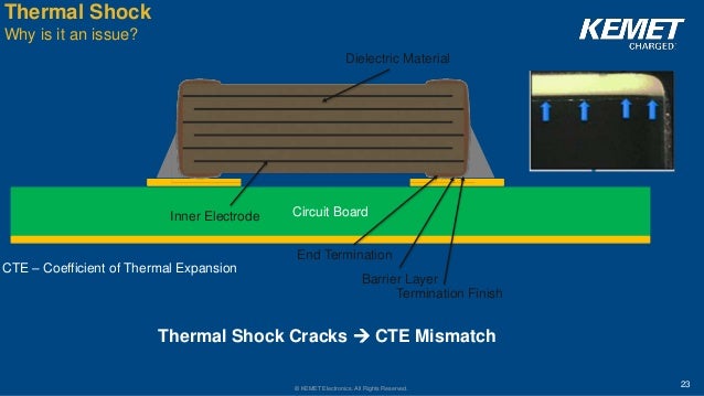
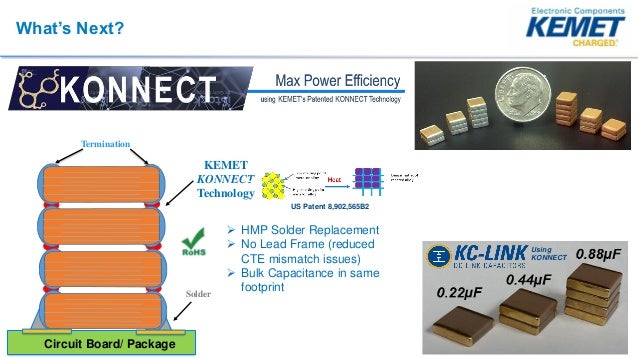
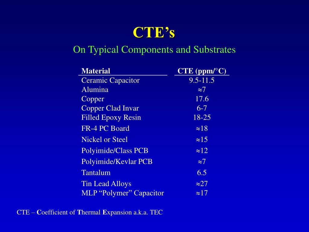
Around 20 ppm c and ceramic with a cte of 10 12 ppm c.
Cte ceramic capacitor.
High Temperature High Voltage Chip Capacitors Hthv From Presidio Components

Thermal Stress On Capacitors Failure Prevention Ee Publishers

Density And Cte For Glass And Glass Ceramic Samples Along With T G Download Table
Http Catalogs Avx Com Advancedceramiccapacitors Pdf

High Reliability Ceramic Capacitors Tackle Harsh Environment Life Critical Applications Electronic Products

Pdf Non Destructive Failure Analysis And Modeling Of Encapsulated Miniature Smd Ceramic Chip Capacitors Under Thermal And Mechanical Loading
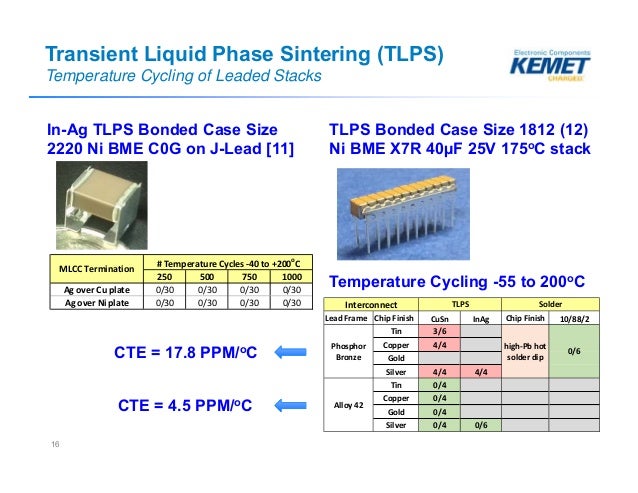
Comparison Between Solders Transient Liquid Phase Sintered Intercon

Coefficient Of Linear Thermal Expansion On Polymers Explained Passive Components Blog

Pdf Effect Of Temperature Cycling And Exposure To Extreme Temperatures On Reliability Of Solid Tantalum Capacitors

How Hot Is Too Hot

What Is Ceramic Pcb

Flex Crack Countermeasures In Mlccs Multilayer Ceramic Chip Capacitors Tdk Product Center

Good Things Come In Small Packages A Capacitor Technology Update Passive Components Blog

Characteristic Parameters Of Aln Ceramic Download Table

Pdf Design Guidelines For Preventing Flex Cracking Failures In Ceramic Capacitors
High Temperature Ceramic Capacitors For Harsh Environments
Ppt Multilayer Polymer Film Capacitors Powerpoint Presentation Free Download Id 592723

Non Destructive Failure Analysis And Modeling Of Encapsulated Miniature Smd Ceramic Chip Capacitors Under Thermal And Mechanical Loading Semantic Scholar

Pdf Lead Free Solder And Flex Cracking Failures In Ceramic Capacitors

Wp A Comparison Between Solders Transient Liquid Phase Sintered Interconnects In High Temperature Multi Layer Ceramic Capacitors Engineering Center

Microwaves101 Temperature Expansion
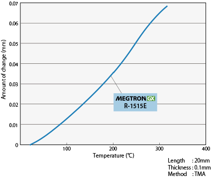
High Elasticity Low Cte Ultra Thin Ic Substrate Materials R 1515e Industrial Devices Solutions Panasonic

Pdf Preventing Ceramic Chip Capacitor Cracking During Printing Wiring Board Bending

Red Dime Sk 1x 50v Ceramic Capacitor Fender Custom Guitars Fender Vintage Capacitors
Source : pinterest.com
