Creo 2 Fillet Sheet Metal Corner

Fillet In Solidworks By Smart Corner بالعربي Solidworks Corner Smart

Solidworks Advanced Fillet Corner Quick Tip Youtube

Solidworks Sheetmetal Close Corner Weld Corner Corner Relief Chamfer Fillet Hindi Urdu Youtube

Autodesk Inventor Tutorial For Beginners Exercise 7 Youtube Autodesk Inventor Autodesk Inventor
Pulling Walls

Solidworks Tutorial For Beginners Exercise 25 Youtube Solidworks Tutorial Solidworks Tutorial
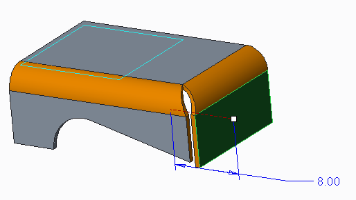
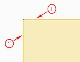
5 create a new flange 4 see that the bend is not nice the green circle how can i make the two red corners together.
Creo 2 fillet sheet metal corner.

Gusset In Solidworks Sheet Metal Design Tutorial 13 Youtube

Solidworks Tutorial For Beginners Exercise 65 Youtube Solidworks Tutorial Solidworks Technical Drawing

How To Create Fillets With Variable Radius Solidworks Tutorials Solidworks Tutorial Solidworks Tutorial

Solidworks Advanced Tutorial Exercise 83 Youtube Solidworks Technical Drawing Tutorial

Distance Across Corners Of Squares Hexagons And Octagons Magnetic Chart Usefulmagnets

Pin On Solidworks
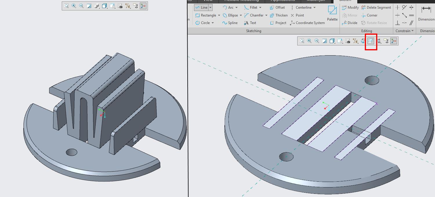
How To Use Fillet And Chamfer In Creo Parametric Sketch

20 Solidworks How To Dimension To The Center Of An Arc Or Fillet Finding The Virtual Sharp Youtube
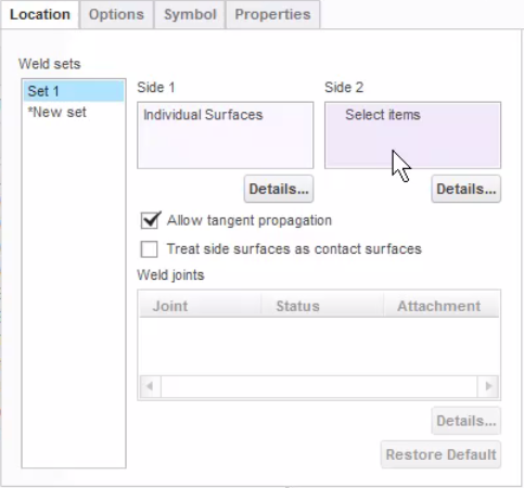
Did You Know Setting Up A Fillet Type Weld With A Ptc Community

Solidworks Tab And Slot Feature For Sheet Metal And Weldments Solidworks Sheet Metal Sheet

Solidworks Tutorial For Beginners Exercise 38 Youtube Solidworks Tutorial Solidworks Tutorial

Full Detailed Design Of The Aluminium Extrusion Die Set Aluminum Extrusion Extrusion Innovation Design

Aluminium Extrusion Mandrel Design Aluminum Extrusion Extrusion Design

Solidworks Tutorial For Beginners Exercise 23 Youtube Solidworks Tutorial Solidworks Tutorial

Solidworks Tutorials Solidworks Basic Tutorials Solidworks Types Fillet Command In Detail Youtube

Solidworks Tutorial For Beginners Exercise 7 Solidworks Tutorial Solidworks Autocad Tutorial
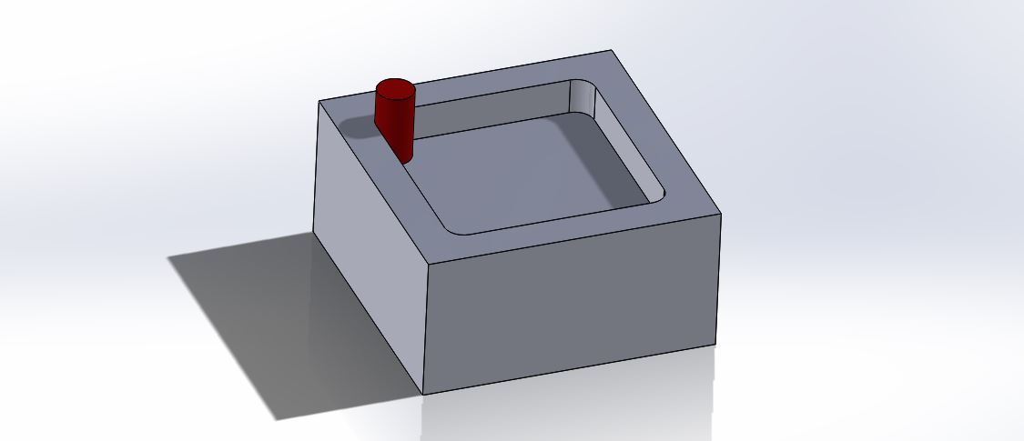
Machining Square Inside Corners Conquer The Nightmare Make It From Metal

Learn Advance Loft Feature With Modeling Practice In Solidworks Youtube
1
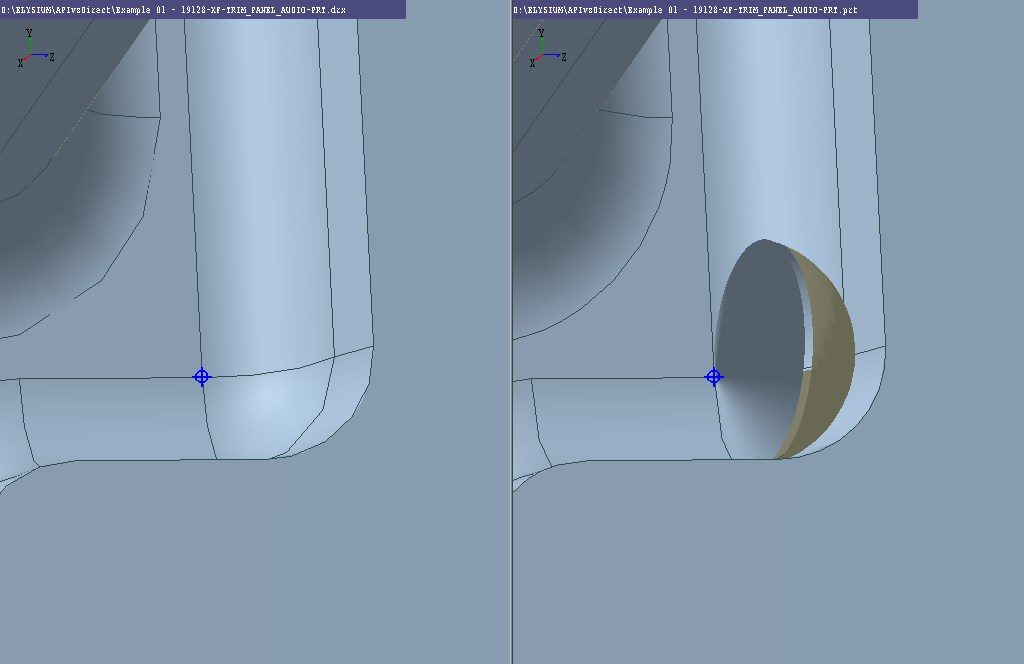
Quality And Validation Of Digital Designs For Aerospace And Defense Blog Elysium En


Solidworks Surface Modeling Creating A K Blend Surface Modeling Solidworks Surface

Fillet Mechanics Wikipedia
How Is Creo 4 Transition Going Ptc Community
Source : pinterest.com
