Create Sheet Metal View Inventor 2018

Inventor Sheet Metal Drawings Youtube

Inventor 101 Sheet Metal Basics Youtube
Https Encrypted Tbn0 Gstatic Com Images Q Tbn 3aand9gcsz1blq Bqzist5mkm7q6l0vc8toknbywxanq Usqp Cau
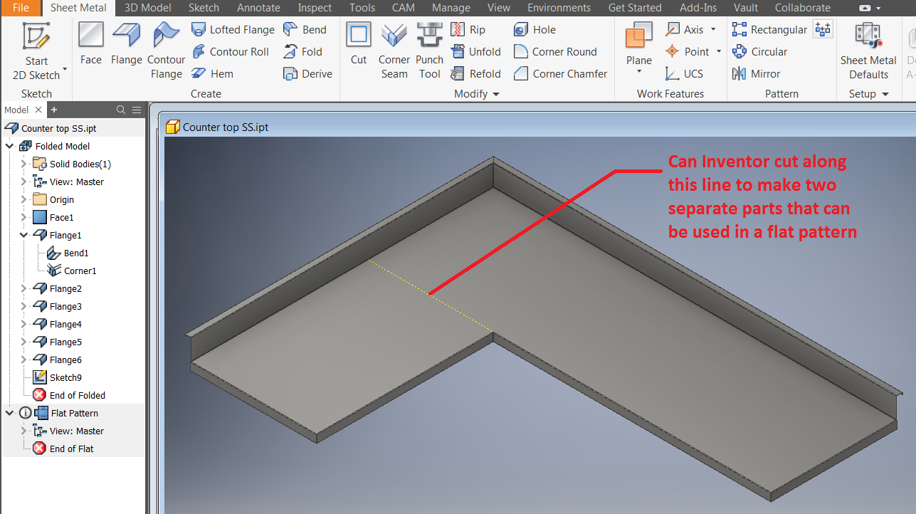
How To Split A Sheet Metal Part While Keeping The Ability To Create A Flat Part In Inventor Inventor 2018 Autodesk Knowledge Network

Solved Sheet Metal View Autodesk Community Inventor

Inventor 101 Sheet Metal Basics Autodesk Virtual Academy Youtube

In the drawing view dialog box select a sheet metal component as file.
Create sheet metal view inventor 2018.
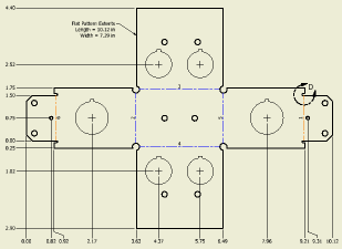
Create A Flat Pattern Drawing View Of A Sheet Metal Part Inventor Autodesk Knowledge Network

Sheet Metal Annotations In Drawings Inventor 2018 Autodesk Knowledge Network

Inventor Sheet Metal From Surface Example Youtube

Inventor Sheet Metal Trailer Box Youtube

Creating A Sheet Metal Emboss In Autodesk Inventor Youtube

Inventor Sheet Metal Contour Flange Tutorial Youtube

Inventor Nesting Utility For Sheet Metal Parts And Manufacturing Youtube

Unfold Storage Tank Shell Autodesk Community Inventor

Autodesk Inventor Sheet Metal Drawing Tutorial Basics Youtube Sheet Metal Drawing Drawing Tutorial Autodesk Inventor

Inventor How To Bend A Part Youtube

Flange Feature In Inventor 2015 Youtube

Autodesk Inventor Sheet Metal Tutorial Basics Youtube

Autodesk Inventor 2018 Ilogic Set Sheet Metal Rule For Selected Components
Inventor 2018 It S Here Inventor Official Blog

How To Draw A Paperclip In Autodesk Inventor 2018 Youtube

Solved Sheet Metal Flanges On Angles Autodesk Community Inventor

Autodesk Inventor Sheet Metal Design Youtube
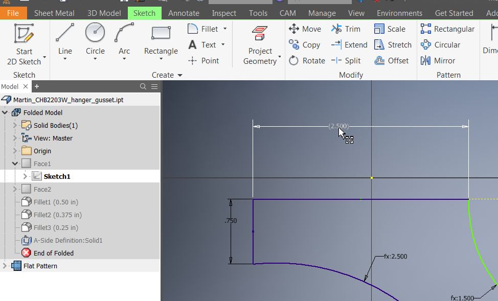
Sketch Dimension Are All Driven Dimensions In Inventor Inventor 2018 Autodesk Knowledge Network
Https Encrypted Tbn0 Gstatic Com Images Q Tbn 3aand9gct3zfazig75npdzpw Xd R1gzsyacdxiq4uba7vtl4pdytnncyc Usqp Cau

Autodesk Inventor 2018 10 Emboss Youtube
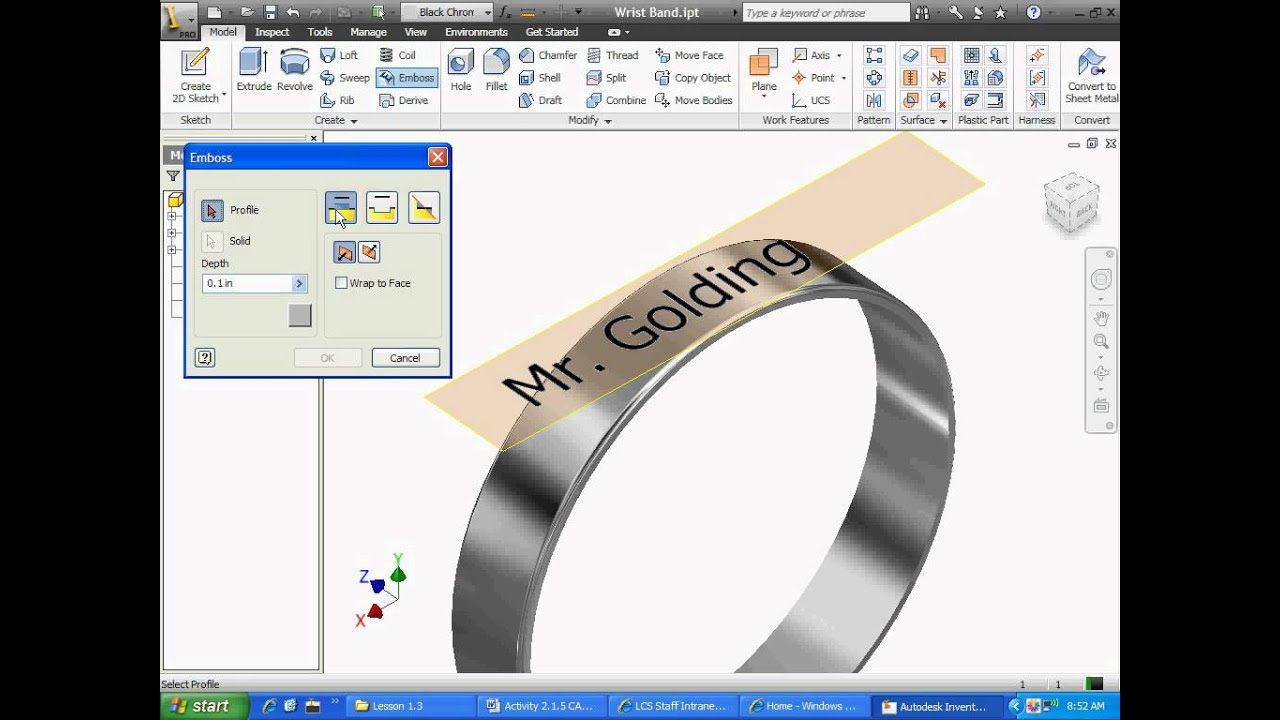
Inventor Emboss Engrave Youtube

Autodesk Inventor Quick Tip Inventor 2018 Chamfer Youtube
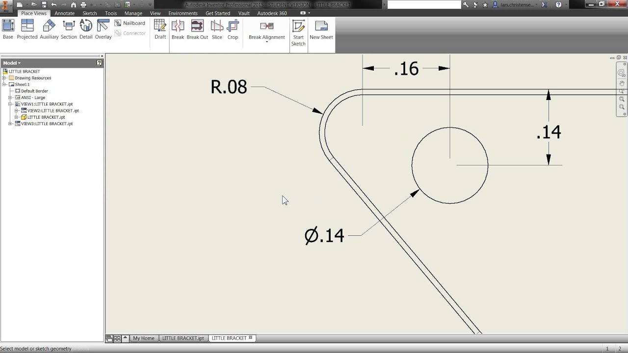
Quick Inventor Tip Get Your Drawing Dimensions Automatically Youtube

Making A Cone For Beginners Using Autodesk Inventor Youtube
Source : pinterest.com
